Long-Range Ocean Radar and
NICT Ocean Monitoring Platform in Sakishima (COMPASS)
The observation area of a surface current vector using Long-Range Ocean Radar (LROR) is shown in the figure. In general, multiple ocean radar observation is required to measure current vectors, so the LROR system consists of two radars: one at Ishigaki Island and one at Yonaguni Island. Each radar can measure the radial current component along the radar beam direction within a fan-shaped area. Current vector can be calculated in the overlapping area of the two fan-shaped areas. To verify the performance of the LROR, an offshore observation buoy named COMPASS (NICT Ocean Monitoring Platform in Sakishima) is moored at the indicated point in the figure.
 |
 |
|
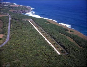
Yonaguni Ocean Radar Facility
|
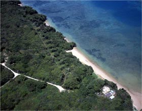
Ishigaki Ocean Radar Facility
|


|